
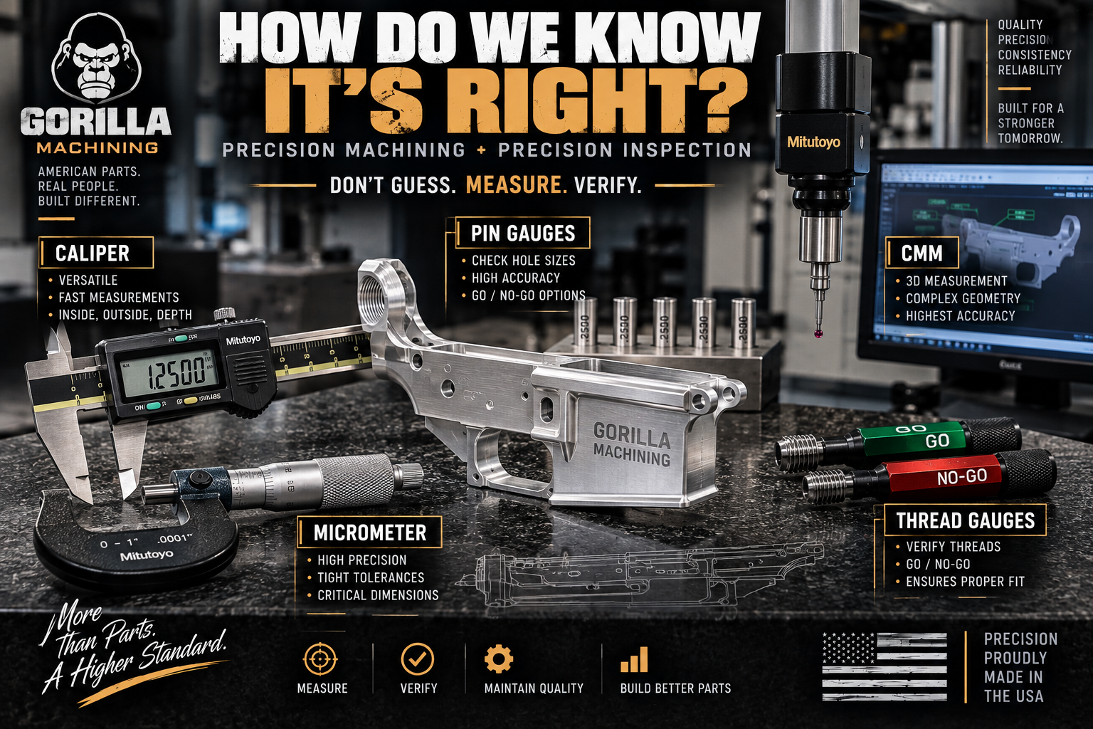
How CNC Parts Are Inspected: Calipers, Micrometers, Gauges & CMMs Explained
A CNC machine can position a cutting tool with incredible precision.
But here's an important manufacturing principle:
Machining a part and proving that the part is correct are two different things.
After a component comes out of the machine, manufacturers need ways to verify that critical features meet their specifications.
That's where quality control and dimensional inspection come in.
Depending on the component and feature being inspected, a machinist or quality-control technician might use everything from a handheld caliper to a sophisticated coordinate measuring machine.
Each tool answers a different question.
Let's look at how they work.
Why Do CNC Parts Need Inspection?
A CNC machine follows a programmed toolpath.
That doesn't mean every component will automatically remain dimensionally identical forever.
Manufacturing variables can change over time.
These include:
Tool wear
Tool deflection
Temperature
Material variation
Fixture condition
Machine condition
Offsets
and the cutting process itself.
Inspection helps manufacturers identify whether those variables are affecting the finished component.
What Is Dimensional Inspection?
Dimensional inspection is the process of measuring a manufactured component and comparing the results with its specified requirements.
Those requirements typically come from:
Engineering drawings and specifications.
The drawing might define:
Diameters
Distances
Hole locations
Threads
Angles
Surface relationships
and acceptable tolerances.
Inspection determines whether the manufactured component falls within those limits.
Nominal Dimension vs. Tolerance
Imagine a drawing specifies a dimension.
That target dimension is often referred to as the:
Nominal dimension.
But manufacturing doesn't generally assume every component will measure to an infinitely exact mathematical value.
Instead, the engineering requirements establish an acceptable range.
That's the:
Tolerance.
For example, conceptually:
Target dimension
?
Upper allowable limit
Nominal dimension
Lower allowable limit
A part measuring within the permitted range can satisfy that dimensional requirement.
Why Tighter Isn't Always Better
Customers sometimes assume that the smallest possible tolerance must automatically produce the highest-quality component.
Not necessarily.
Tighter tolerances can require:
Additional machining time
More inspection
More expensive equipment
Greater process control
and potentially higher manufacturing cost.
Engineers therefore assign tolerances based on what the feature actually needs.
Precision should have a purpose.
Making every dimension unnecessarily tight isn't automatically better engineering.
Tool #1: Digital Calipers
One of the most recognizable inspection tools in a machine shop is the:
CALIPER
Digital calipers can be used for many general measurements.
Depending on the design, they can measure:
Outside dimensions
Inside dimensions
Depth
and certain step measurements.
They're quick, versatile, and extremely useful.
Are Calipers the Most Accurate Measuring Tool?
No.
Calipers are excellent general-purpose instruments, but other tools can provide greater resolution or be better suited to specific measurements.
This is an important principle:
The measuring tool should match the measurement being made.
A caliper isn't automatically the correct tool simply because it can physically reach the feature.
Tool #2: Micrometers
For more precise dimensional measurements, machinists often use:
MICROMETERS
Micrometers are designed to measure dimensions very accurately over a specific range.
Different micrometers exist for different applications.
Common examples include:
Outside micrometers
Inside micrometers
and
Depth micrometers.
Caliper vs. Micrometer
Both measure dimensions, but they serve somewhat different roles.
| Caliper | Micrometer |
|---|---|
| Highly versatile | More specialized |
| Measures several feature types | Usually designed around a particular measurement |
| Fast general inspection | Useful for higher-precision measurement |
| Wide measuring range | Smaller dedicated range |
| Common shop-floor tool | Common precision inspection tool |
One doesn't replace the other.
A good inspection department uses the appropriate tool for the feature.
Tool #3: Pin Gauges
Suppose you need to determine whether a machined hole is within its allowable diameter.
One useful inspection method involves:
PIN GAUGES
Pin gauges are precision-ground cylindrical gauges produced in known sizes.
Rather than trying to measure the inside of a small hole with caliper jaws, an inspector can determine which known gauge sizes fit appropriately.
This can provide a very effective method for evaluating hole size.
GO and NO-GO Inspection
Gauging often uses the concept of:
GO
and
NO-GO.
The basic idea is straightforward.
A GO gauge evaluates one boundary of the acceptable condition.
A NO-GO gauge evaluates the opposite boundary.
When used correctly, this allows an inspector to quickly determine whether a feature falls within defined limits without needing to obtain a numerical measurement every time.
Tool #4: Thread Gauges
Threads are another feature where specialized gauges can be extremely useful.
As we discussed in our thread-machining blog, a random mating component isn't necessarily a calibrated inspection tool.
Manufacturers can use:
Thread plug gauges
for internal threads and
Thread ring gauges
for external threads.
These help evaluate threaded features against known dimensional limits.
Why “It Screws Together” Isn't Enough
Imagine testing a threaded component using another production component.
The two pieces fit.
Does that prove both are within specification?
Not necessarily.
Both components have their own tolerances.
That's why calibrated gauges are valuable.
They provide a known reference.
Fit testing and dimensional verification aren't always the same thing.
Tool #5: Height Gauges
A height gauge is another common precision-inspection instrument.
It can be used with a flat reference surface—often a precision surface plate—to measure or compare feature heights and locations.
Depending on the setup, height gauges can help inspect:
Feature positions
Step heights
Distances
and other dimensional relationships.
What Is a Surface Plate?
Walk into a quality-control department and you may see a large, extremely flat stone table.
That's often a:
GRANITE SURFACE PLATE
A surface plate provides a highly controlled reference plane for dimensional inspection.
Why granite?
Among other advantages, precision granite can provide excellent stability and wear characteristics for metrology applications.
The important idea is that measurements need a reliable reference.
Tool #6: Bore Gauges
Internal cylindrical features can require more specialized measurement.
A bore gauge can help evaluate internal diameters.
Depending on the equipment, inspectors can use bore gauges to evaluate characteristics such as:
Diameter
Variation
and potentially changes along a bore.
Again, specialized geometry often requires specialized measurement equipment.
Tool #7: Optical Inspection
Not every feature is easiest to inspect through physical contact.
Optical measuring systems can use cameras, magnification, and software to evaluate component geometry.
These systems can be particularly useful for:
Profiles
Edges
Small features
and complex two-dimensional geometry.
The component can be magnified dramatically while measurement software evaluates the feature.
And Then There's the CMM
One of the most impressive tools in dimensional inspection is the:
COORDINATE MEASURING MACHINE
Usually shortened to:
CMM
A CMM measures the geometry of a component using coordinate data.
Instead of measuring only one simple distance, the system can evaluate the position and relationship of numerous features in three-dimensional space.
How Does a CMM Work?
Many traditional CMM systems use a precision probe.
The machine moves the probe around the component and records points on selected surfaces.
Those points create coordinate information.
Software can then use that information to evaluate geometric characteristics.
This allows manufacturers to inspect complex relationships that can be difficult to evaluate with handheld tools alone.
What Can a CMM Measure?
Depending on the machine, software, probing system, and inspection program, a CMM can help evaluate features such as:
Hole location
Diameter
Distance
Flatness
Parallelism
Perpendicularity
Position
and complex geometric relationships.
This is where metrology becomes extremely powerful.
What Is GD&T?
Once you start discussing CMM inspection, another term appears frequently:
GD&T
That stands for:
Geometric Dimensioning and Tolerancing.
GD&T is a standardized engineering language used to define allowable variation in component geometry.
Instead of specifying only simple dimensions, engineers can control relationships such as:
Position
Flatness
Perpendicularity
Parallelism
Runout
and other geometric characteristics.
Why Geometry Matters
Consider two holes.
Both could have the correct diameter.
But what if one hole is located in the wrong position?
Measuring only its diameter wouldn't reveal the entire problem.
Manufacturing quality therefore isn't only about:
“How big is this feature?”
Sometimes the question is:
“Where is this feature relative to everything else?”
That's where geometric inspection becomes important.
What Is a Datum?
We introduced datums in the workholding blog.
They're just as important in inspection.
A datum establishes a reference from which other geometric relationships can be evaluated.
Engineering drawings may establish multiple datum references to define how the component should be oriented for measurement.
That means manufacturing and inspection are speaking the same geometric language.
First Article Inspection
When a new manufacturing process begins, manufacturers may perform a more comprehensive inspection of an initial component.
This is commonly associated with:
First Article Inspection.
The purpose is to verify that the manufacturing process can produce the required geometry before full production continues.
Exact procedures vary depending on the manufacturer, industry, and quality requirements.
In-Process Inspection
Inspection doesn't necessarily happen only after the component is completely finished.
Manufacturers may inspect features during production.
This is:
In-process inspection.
For example, a critical dimension might be checked after one machining operation before the component moves to another stage.
This can catch problems earlier.
Final Inspection
Once machining and other required manufacturing operations are complete, a component may undergo final inspection.
Depending on the product, this can include a combination of:
Dimensional checks
Gauge checks
Visual inspection
Thread inspection
Surface inspection
and verification of other product requirements.
The exact inspection plan depends on the component.
Why Sampling Is Used in Manufacturing
In high-volume manufacturing, measuring every dimension on every component can be impractical.
Manufacturers may therefore use documented sampling plans for certain inspections while checking critical features more frequently.
The appropriate approach depends on the manufacturing process, risk, specifications, and quality system.
The important point is:
Quality control is a process—not simply someone looking at the part before it gets boxed.
Calibration Matters
Here's something customers rarely hear about.
The measuring equipment itself needs to be trustworthy.
Calipers, micrometers, gauges, and other inspection equipment can be subject to calibration and verification programs.
Otherwise, you could have a perfectly machined component being judged by an inaccurate measuring instrument.
You can't verify precision with an untrustworthy reference.
Temperature Can Affect Measurement
Metal expands and contracts with temperature.
For everyday objects, that change may seem insignificant.
But precision metrology can operate at a scale where temperature matters.
High-precision inspection environments may therefore control temperature and allow components to stabilize before certain measurements.
This shows just how deep precision manufacturing can go.
Why Inspection Records Matter
Manufacturers can document inspection results to help monitor their production process.
Over time, those measurements can reveal trends.
For example, dimensions gradually moving toward one side of a tolerance range may indicate:
Tool wear
Offset changes
Fixture issues
or another process variable.
Catching a trend before components become nonconforming is a major goal of good process control.
Quality Control vs. Quality Assurance
These terms are sometimes used interchangeably, but they describe related concepts.
Quality Control
Focuses heavily on inspecting and evaluating the product or process output.
Quality Assurance
Is broader and involves the systems and procedures intended to consistently produce acceptable results.
In practical manufacturing, both work together.
Why Inspection Matters for AR Components
A precision-machined component can contain numerous features that interact with other components.
Those relationships make dimensional consistency important.
The finished part might look perfect from the outside.
But appearance can't tell you whether every important dimension is correct.
That's why manufacturing quality needs more than a good-looking finish.
It needs:
Measurement.
Frequently Asked Questions
What is the most common machinist measuring tool?
Calipers and micrometers are among the most recognizable, but the appropriate tool depends on the feature being inspected.
Is a micrometer more precise than a caliper?
Micrometers are generally designed for higher-resolution measurement within a more specialized range, while calipers offer greater versatility.
What is a pin gauge?
A pin gauge is a precision-sized cylindrical gauge commonly used to evaluate hole dimensions.
What is a GO/NO-GO gauge?
It's a gauge system designed to quickly determine whether a feature falls within specified dimensional limits.
What does CMM stand for?
Coordinate Measuring Machine.
Why use a CMM?
A CMM can evaluate complex three-dimensional geometry and relationships between features that may be difficult to verify using handheld instruments alone.
What is GD&T?
GD&T stands for Geometric Dimensioning and Tolerancing, a standardized system for defining allowable geometric variation on engineering drawings.
Conclusion
Precision machining doesn't end when the CNC doors open.
That's when another important process begins:
Verification.
A manufacturer may use:
Calipers
Micrometers
Pin gauges
Thread gauges
Height gauges
Optical systems
and
Coordinate measuring machines
to determine whether components meet their required specifications.
Because in precision manufacturing:
Making the dimension is only half the job.
The other half is proving you made it.

